|
SHMRRC Free-Mo Accessory Power
|
|
The Free-Mo standard suggests an accessory power bus that can be used for supplying power for lighting and other layout needs. Many of our modules use this bus but many do not. Please look over these notes and consider adding such a bus to your module before the next time we display our layout. |
The Free-mo Wiring Standard, which can be seen here: http://www.free-mo.org/standard#4 describes how modules should be wired. The items of interest for the accessory bus are :
S4.2 Track and Accessory Bus wire shall be 14 AWG stranded or larger wire.
S4.2.1 Modules in existence prior to 1 July 2015 may have track and Accessory Bus wire that is 18 AWG. It is highly recommended that they are upgraded to 14 AWG stranded or larger wire.
S4.11 Accessory power shall be approximately 16 volts AC or DCC. The bus is wired straight through. A bridge rectifier and filtering capacitor may be used to convert AC or DCC signal to DC. Applications that require AC or DCC signal may utilize power directly from the bus. (FAQ S4.11)
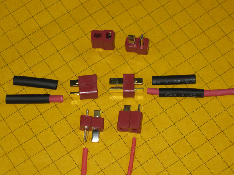
The implementation that has been installed on some of our modules uses the same "Deans" connectors that we use with our DCC bus wiring.
The wire that runs from one end of the module to the other should be 14 or 18 gauge. The smaller the gauge (and the thicker the wire) the better.
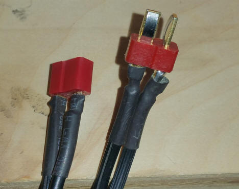
It is ideal if you supply a male and a female connection at each end of the module. This can be done by wiring two separate cables as shown here
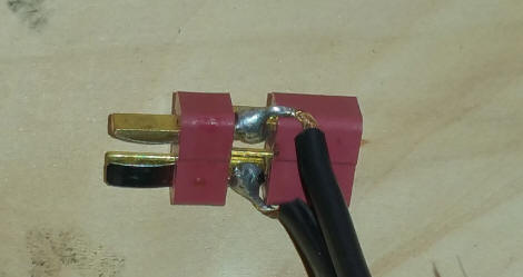
or by soldering a male and a female Dean's plug to one wire.
To differentiate them from the DCC wiring bus they can be marked with a label, piece of colored tape or some other identifier.
Free-mo suggests either DCC or AC to be placed on the accessory bus. I have been powering my accessories (and the switchback system) with 19 volts DC at approximately 2 amps.
To tap into and use this power on your module it is suggested that you use a simple circuit composed of a bridge rectifier and filter capacitor. This has several advantages. First, it allows you to ignore polarity on the accessory bus. In addition it allows us to, in the future, run the bus with AC.
The suggested circuit is shown here:
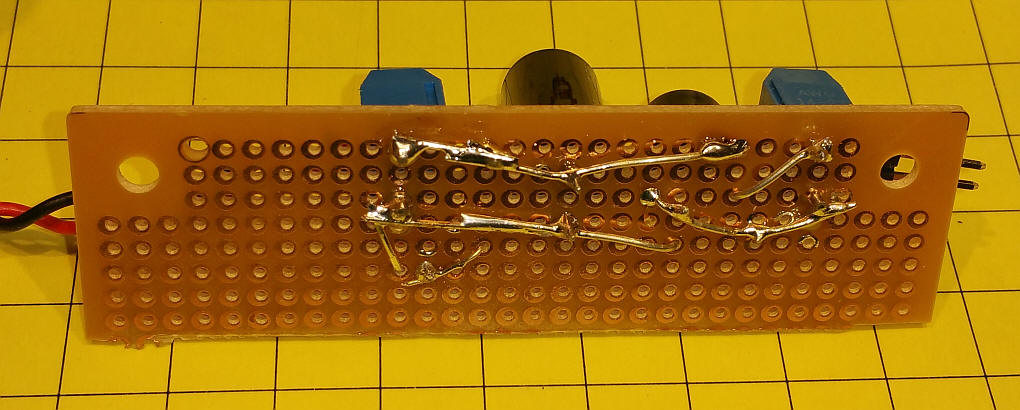
Here is the finished circuit, top and bottom view. The power from the accessory bus comes in at the left and DC comes out at the right.
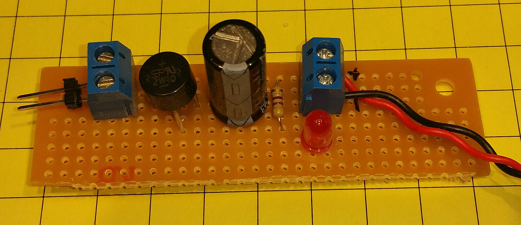
The bridge rectifier should be sized to handle you needs. 1 amp should be plenty for most of us. The capacitor is an electrolytic. Its voltage rating should be more than the voltage on the Accessory Bus. 25 volts is a safe choice. Use at least 1000 uf. More if you have a larger cap available and plan on pulling more than 1 amp.
If your circuit can operate from 18 or 19 volts you can power it directly from the output of this circuit. If you need a lower voltage, such as 12 or 7 or 5 volts, use a switch mode power converter like this one:
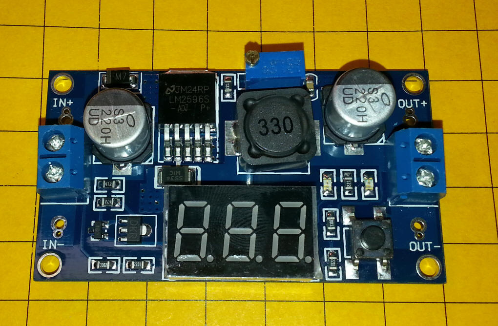
They can be purchased from eBay and other vendors for only a few dollars and allow you to dial in just the voltage you need. As an added bonus they create very little heat. For more information see: http://www.trainelectronics.com/artcles/DC-DC_Converter/SwitchMode.htm